


Hello, my loyal blog post readers, in this my third installment of our SD-WAN series I am going to walk you through how our vEdge router locates, communicates and authenticates itself onto our SD-WAN fabric. Along the way we will take a look at a few packets captures and command line output to see what is going on under the hood.
In previous posts we were introduced to the architectural components of our SD-WAN, and to the lab environment that I will be using to demonstrate my examples in this series. If you have not already done so I highly recommend checking them out (how modest of me) before reading on as we will be leveraging some of the information presented in those posts.
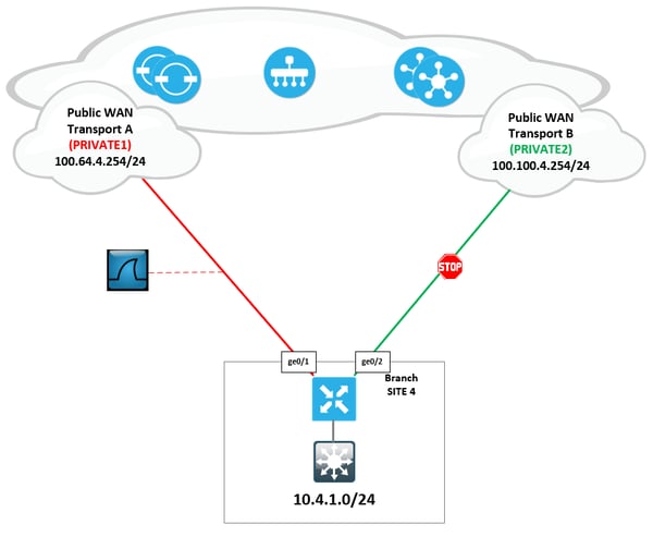
All command output will be taken from our labs site 4 vEdge “e4”. To simplify the output, I have disabled the ge0/2 interface attached to our second WAN transport (PRIVATE2). This leaves us with a single WAN transport (PRIVATE1) connected through interface ge0/1.
The vEdge bringup can be boiled down to 5 hopefully simple steps shown in the diagram below.
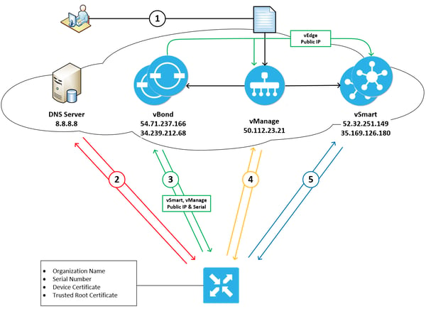
Step1: The automatic validation and authentication of vEdge that occurs during the bringup process can happen only if the vSmart controllers and the vBond orchestrators know the serial numbers of the vEdges that are permitted onto the network. The vSmart and vBond controllers learn these serial numbers through the vEdge authorized list which can be downloaded from the customers support portal and then uploaded to vManage, which then in turn distributes the list to our vSmart and vBond controllers. We saw this process in part 2 of the series when we were deploying site 4’s vEdge.
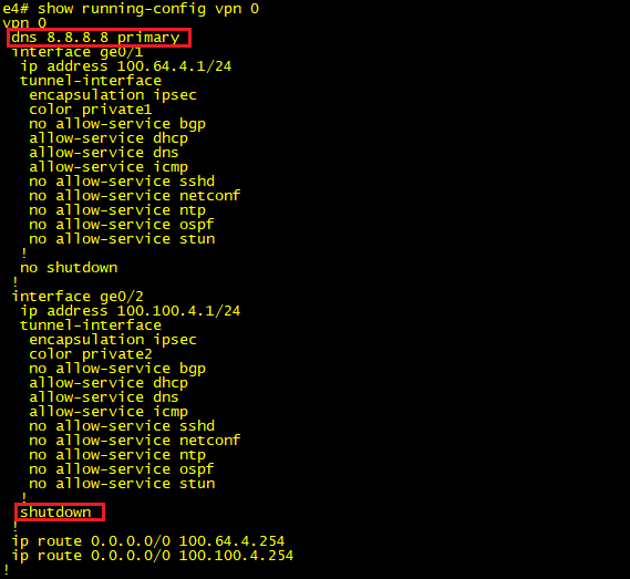
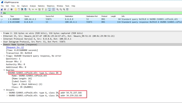
Step2: Our vEdge needs to initiate a connection to our fabric orchestrator (vBond), to do this we use our good old friend DNS. Our bootstrap config needs to contain the FQDN of our vBond nodes, along with the address of the DNS server that we will be using to resolve this name. The images below were taken from our vEdge and shows the configuration lines that we applied to satisfy this step.
The first two packets in our capture show this DNS query\answer pair. So we now know our two vBond public ip addresses 54.71.237.166 & 34.239.212.68, it’s time to put them to good use and start ourselves a little conversation.
Step3: Every vEdge’s dream is to one day talk to its vManage server so it can fulfill its destiny of having a full configuration sent to it, and to partner with a vSmart controller so that it can truly experience what it is like to be part of an SD-WAN fabric. Well to do that we need our good friend vBond to authenticate us and orchestrate those connections by sharing with us the IP addresses and serial numbers of the vManage and vSmart nodes in our organization. vBond also lets us know if we are behind a NAT device and if so what our outside global address is. This will come in handy when we start bringing up our data plane tunnels, but that’s for another blog post. While also sharing all this great info with us vBond also shares with vManage and vSmart our vedge public ip address. This is so they are prepared to receive our call when we come a knocking, you see our fabric nodes all work on a white list trust model. That is to say, if your name is not on the list then you are not coming in (takes me back to my clubbing days).
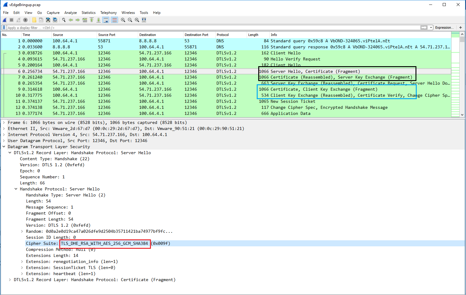
First, we need to build a secure tunnel over which we will perform mutual authentication between our vEdge and vBond. We do this using DTLS (Datagram Transport Layer Security) tunnels encrypted using RSA and AES256 ciphers.
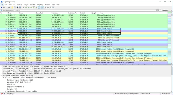
In the below capture we can see that our vEdge initiates a DTLS connection to one of the DNS returned vBond ip addresses. The vBond nodes sends us its certificate (black box) and we in return send it our certificate (blue box).
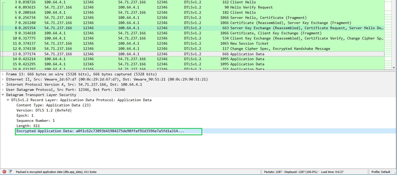
Both nodes leverage their installed root ca certs to validate that the peers received certificate is indeed good. Once confirmed we settle on our cipher suite (red box) which will be used to encrypt our communication between the two nodes (green box) from here on out .
During the certificate validation phase of the above communication a couple of extra authentication checks are made to ensure that we are joining the correct fabric. The vBond looks into the vEdges certificate and checks the serial number contained in it against the authorized list it received from vManage in step 1. If the serial number is not on the list, then the tunnel is torn down and an error is logged. The below output shows our vEdge certificate highlighting, where the serial number is located within it.
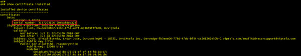
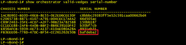
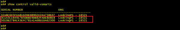
From our vBond we can run the below command to see a list of currently authorized vEdge serial numbers. Note that the last line (red box) matches the serial number in our vEdge.
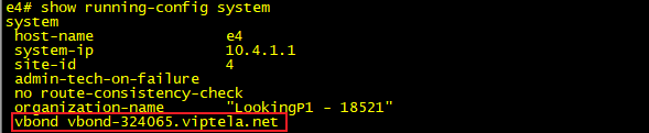
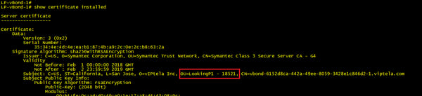
On our vEdge end of the peering we also take a look at the certificate presented to us from vBond and extract the organization-name from it. This needs to match the org name that we have configured locally as part of our bootstrap config. The organizational name must be identical on all devices that make up the fabric (this name is case-sensitive).
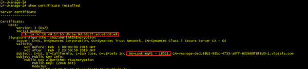
The below output shows our vBond installed certificate, highlighting where the organization name is located within it.
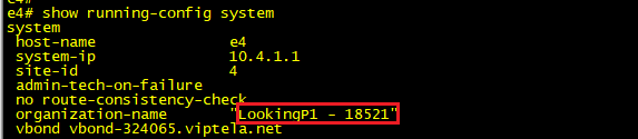
This org name is checked against the one configured under the system settings of the vEdge. See below that this matches the string presented in the vBond certificate above.
With our tunnels encrypted and both nodes authenticated the vBond can now proceed with sending our vEdge the IP addresses of our organizations vManage and vSmart nodes along with their serial numbers. At this point the vBond also relays to vManage and vSmart that a new vEdge has joined the network and that they should expect an incoming communication from its public address. At this point the DTLS tunnel between our vEdge and vBond is no longer required so it is torn down and the vEdge proceeds to steps 4 and 5.
Steps 4 and 5: Steps 4 and 5 really occur in parallel, so we will address them both under one section. Having received our vManage and two vSmart ip addresses and serial numbers from vBond our vEdge once again initiates a DTLS connection to the three nodes.
Certificates are exchanged, and mutual authentication takes place between vSmart, vManage and vEdge.
vSmart and vManage validate vEdges certificate using their root ca trust list and extract the serial number from it to compare against their authorized list.
In return vEdges validate vSmart and vManage certificate using its root ca trust list and extracts the serial number and organization name from it to compare with its authorized list and configured org name.
Below is output from our vEdge showing its authorized list of vSmarts and vManage nodes. This is the list that was provided by vBond in the step above.
vManage Certificate, note that the serial number matches our list from the vEdge above.
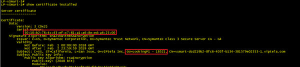
vSmart Certificate, note that the serial number matches our list from the vEdge above.
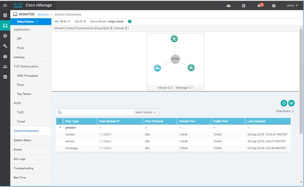
We should now have three permanent DTLS tunnels from our vEdge to 1 vManage and 2 vSmarts. We can confirm this from the command line:

Or alternatively we can get the same information from our vManage dashboard.
The vManage tunnel is used to push config to our vedge and also to receive statistics, while our vSmart DTLS tunnels facilitate the propagation of our SD-WAN policies via OMP (More to come on this in upcoming posts).
What's Next?
Ok that’s a wrap for now. Next time we will take a look at some of the settings we can tweak regarding these control plane connections and see what happens when we have a failure in the control plane.
Until then may your overlays and underlays routing never get leaked and your WAN bandwidth be plentiful and lossless.


Written By: Chris Marshall, LookingPoint Senior Solutions Architect - CCIE #29940
Check out our awesome tech talk on SD-WAN:
If you are interested in having LookingPoint install SD-WAN into your network, feel free to contact us here!