


That title is not true, but I just could not come up with a better one. I like rhyming phrases I guess.
Recently I had the pleasure of reacquainting myself with an old layer two extension protocol friend, by the name of OTV and figured this experience might make a good blog post.
One of our customers was in the process of moving data centers and was concerned that some of there applications may not respond well to having there IP addresses changed. Sensibly plan A was always to readdress all migrated workloads, but its never a bad idea to have a backup plan, and that’s where OTV came in.
Its been a few years since I last worked with OTV. Back then it was an exclusive feature of the Nexus 7K platform running the NXOS operating system. Since then OTV has been extended to work on a select few IOS-XE platforms, namely the ASR, ISR 4451 and the CSR. Since this customer was only looking at deploying OTV as a short-term safety net then it made sense to not invest in additional hardware and instead go with the subscription based virtualized option of the Cisco Cloud Services Router (CSR).
As part of this project I mocked up the customers environment in the LP lab. We will utilize this lab to look under the hood at how OTV works, but before that lets get everyone up to speed with some OTV quick facts and terminology:
What is OTV?
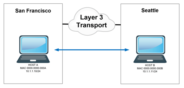
OTV stands for Overlay Transport Virtualization. This technology allows us to extend a layer 2 ethernet domain across any layer 3 transport network. Examples of layer 3 transport networks could be your MPLS WAN or even the internet. In a nutshell it allows us to have hosts in separate geographical locations communicate directly at layer 2. In the example below Host A in San Francisco and Host B in Seattle are both addressed from the same layer 3 subnet 10.1.1.0/24. OTV allows these host to believe that they are part of the same layer 2 domain. Frames sent from Host A to B will have a destination MAC of 0000.0000.000B.
How does it work?
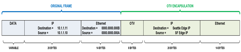
OTV encapsulates layer 2 frames inside of layer 3. Yes, it’s yet another tunneling protocol. In the case of our example above Host A’s frame will be encapsulated with additional OTV (8 byte), outer IP (20 byte) and outer layer 2 (14 byte) headers, resulting in a total of 42 Bytes of overhead. The OTV device in Seattle strips off this encapsulation and delivers the original frame to Host B. Host A and B are none the wiser and continue to communicate as though they are L2 adjacent.
We will take a closer look at the OTV header and its effects on fragmentation when we look at some packet captures later in the series.
The decision to encapsulate is made by OTV only if it has knowledge that a MAC address resides at a remote site. To gain this knowledge OTV needs a control plane protocol to advertise MAC addresses. More on this later.
Is it a standard protocol?
OTV is a Cisco proprietary protocol. A few Internet drafts were submitted to the IETF, but it never progressed to full RFC status. The last draft (version 4) can be found here. So, if you want to deploy OTV you will need Cisco equipment at both ends of our tunnels.
Why would I use OTV to extend L2?
OTV main use case is for virtual machine workload mobility (vMotion). As mentioned above it is transport agnostic and is purpose built for data center interconnect (DCI) connectivity. It also has built in scaling and protection mechanism (STP, ARP and Unknown unicast suppression).
Alternative solutions to layer 2 extension such as dark fiber (CWDM/DWDM), L2TPv3, VPLS or bridging over GRE, either do not contain the protection/scaling benefits mentioned above or they require a lot of manual tuning. OTV works right out of the box 😊. Its also worth noting that OTV is deployed on our CPE equipment meaning we maintain control of the configuration. Sol
OTV Edge Device:
Name of a router that is running OTV. We need a minimum of one Edge device at each site where we want to extend layer 2.
OTV Authoritative Edge Device (AED):
OTV Edge router that is actively extending a VLAN from a site. If we only have a single OTV Edge device at our site it will be the AED. If we have multiple Edge devices for redundancy, then the AED role will be negotiated per extended VLAN.
Extend VLANs
VLAN being extended between our DC’s via OTV
Site VLAN
Local site VLAN used to negotiate OTV parameters between Edge devices within a site. The site VLAN must not be added to our extended VLAN list.
OTV Site Identifier
Unique 48-bit ID per DC site.
OTV Join Interface
Layer 3 interface used as the source/destination of our overlay tunnels
OTV Internal Interface
Layer 2 interface used to learn MAC addresses of host in the extended VLANs. This interface should also carry the Site VLAN.
OTV Overlay Interface
Logical interface where the majority of OTV commands are applied.
OTV Adjacency Server
Used for discovery of overlay environment. Edge Devices will register with the adjacency server on initialization and receive a list of other Edge Devices. This list is used to build OTV peering’s and to replicate multicast and broadcast packets.
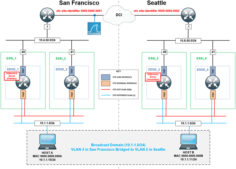
Now we have our OTV terminology down, we can look at our lab environment. The diagram below shows our setup and where each of our OTV components listed above reside. In my next installment I will show you how to configure OTV and look at some packet captures to see what is going on under the hood.
If you need help with moving your data centers, please reach out to us and we can help make that process easy for you!

Written By: Chris Marshall, LookingPoint Senior Solutions Architect - CCIE #29940