


Cisco SD-WAN (formally Viptela) is quickly becoming the go to WAN solution for Cisco customers. As companies are looking to replace their aging DMVPN solution, Cisco SD-WAN has become the logical choice. Companies can stick with the same ISR platform running IOS-XE that they already know, and in some cases can upgrade their existing routers to work with SD-WAN. But this blog isn’t a sales pitch for how good SD-WAN is, this is a tutorial on the process of Plug and Play onboarding.
So what is Plug and Play (PnP) onboarding, and how does it relate to SD-WAN. Plug and Play is the mechanism used for ISR and CSR routers to discover, bootstrap, and ultimately call home to a particular set of SD-WAN controllers. This process is different than Viptela’s original onboarding server, called Zero Touch Provisioning (ZTP), if you have an old Viptela vEdge router the ZTP process is how that device is onboarded. In this blog we will only cover the Cisco PnP process using Cisco ISR routers. To give a quick overview of the SD-WAN controller and onboarding process; there are three types of controllers:
- vManage– This is the centralized management controller. This is the machine that you as the administrator will log into to configure all of the devices. Additionally this is also pushes policy changes to the next controller.
- vSmart– This is the centralized control plane controller. All of the vEdges need to connect with the vSmart controllers in order to get updates on routing, IPSec keying info, topology changes, and security mechanisms.
- vBond– This is the onboarding controller. This controller is in charge of providing vEdges the information needed to connect to the appropriate vManage and vSmart instances. As we will see, this is the only information needed in the bootstrap configuration that will be placed on the vEdge router.
SELF-SERVICE PORTAL
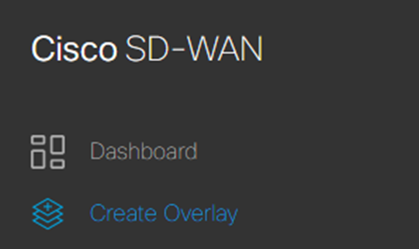
If your company is new to SD-WAN and don’t have a set of controllers provisioned for your organization, then the very first process will be to create a new overlay. Obviously if your overlay is already provisioned then skip this step and go right into looking up the overlay info using the same self service portal. Go to https://ssp.sdwan.cisco.com and login using your Cisco CCO account. In the upper left corner hit the “burger” to reveal the side menu, select “Create Overlay”
From there go though the short wizard linking your companies smart account, and choosing which cloud provider (AWS or Azure) you want your controllers configured in. NOTE: At the time of this writing there is no difference between choosing either AWS or Azure, it is purely preference. For a fully detailed procedure, check out cisco’s configuration guide: https://www.cisco.com/c/en/us/td/docs/routers/sdwan/configuration/self-serv-por/sdwan-ssp/manage-overlay-networks.html
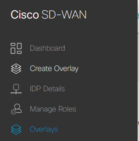
Once the overlay is provisioned, or if you already had the overlay provisioned, navigate to “Overlays”
In the overlays menu choose your smart account, (note that if your CCO is attached to multiple accounts this is where you can choose which vManage account to use) this will open the overlay details page. On this page we need to do three things:
- Write down the link for vManage. This is the link used to configure all of SD-WAN. It is good practice for you to create a CNAME DNS record pointing to this link, so that you can create something memorable for your administrators to connect to.
- Write down the vBond DNS FQDN. This will be used later when creating the bootstrap file.
- Click on the “Inbound Rules” box. This links to a page where you need to add the public
- IPs that are allowed to connect to vManage. Failing to add your public IP here will mean that you cannot connect to the vManage webpage.
At this point you have all the info you need from the Self-Service Portal.
PLUG AND PLAY PORTAL
The point of the PnP server is to provide a list of approved routers that can associate with the SD-WAN controllers. Each ISR router has a built in chip that holds an identity cert. SD-WAN uses cert based authentication to verify that the routers that are trying to establish a connection to the controllers are in fact approved to do so.
If you purchased new routers as part of an SD-WAN bundle, there is a chance that those routers are already in your companies PnP portal, in which case you can skip this section. If not, then you will need to manually add the router to the portal so that vManage and vBond will accept the certificate. Either way its good practice to check that the routers are in the portal.
To check, navigate to https://software.cisco.com and sign in with your Cisco CCO. You are probably familiar with this site if you had to license a device with the smart licensing server. Scroll down towards the bottom of the home page, and under the “Smart Licensing” section you will see the Network Plug and Play link. Click “Manage devices”

Next make sure the correct Smart account and Virtual account are selected in the upper right corner, then under the “Devices” tab you should see a list of all the routers registered with PnP. If you do not see your router, or any router for that matter then you will need to manually add the router(s). Luckily this is pretty easy to do:
- First click on “add devices…”

- Then download the sample CSV. Use this CSV to add all of the routers at once. Keep this page open cause once you are done you will browse and import the CSV here.

In the CSV the following fields need to be filled out:
- udiProductId
- udiSerialNumber
- controllerProfile
- Certificate SN
I also like to fill out the description field with the routers eventual hostname so that its easier to manage in the future. For the controller Profile field you need to enter the value VIPTELA-CLOUD-HOSTED-PROFILE. To find the information needed in the other three fields you will need to connect to the cli of the router.
ROUTER CLI COMMANDS
In order to get the three pieces of data for the CSV file you will need to run two commands on the routers you want to add to PnP. Connect to the router and run the following two commands.
To get the udiProductId and udiSerialNumber data you just need to run a single command:
router#show license udi
UDI: PID:<udiProductId>,SN:<udiSerialNumber>
To get the Certificate SN run the command:
router#show crypto pki certificates
Certificate
Status: Available
Certificate Serial Number (hex): <Certificate SN>
Certificate Usage: General Purpose
Issuer:
o=Cisco
cn=High Assurance SUDI CA
Subject:
Name: <udiProductId>
Serial Number: PID:<udiProductId> SN:<udiSerialNumber>
cn=<udiProductId>
ou=ACT-2 Lite SUDI
o=Cisco
serialNumber=PID:<udiProductId> SN:<udiSerialNumber>
Validity Date:
start date: <start date>
end date: <end date>
Associated Trustpoints: CISCO_IDEVID_SUDI
One thing to note is that routers will have multiple certificates installed. Make sure you add the serial number for the identity certificate that was issued by Cisco with the High Assurance SUDI CA cn.
Once you have the CSV filled out and saved, upload it to the PnP page where the CSV was downloaded and hit next. The next screen will ask you to verify all of the data and then submit to add those routers to the PnP server. Verify the routers were added by looking at the “Devices…” tab.
SYNC TO VMANAGE
The next thing to do is to sync the routers from PnP into vManage. Login to your vManage instance using the link provided in the self-service portal, and navigate to Configuration > Devices.

Under the “WAN Edge List” tab click the “Sync Smart Account” link on the top bar of the page. You will be asked to sign into the smart account using a username and password. These credentials are not saved by vManage, only used for the single sync task, so it is ok to use the same CCO used to add the devices to PnP.

At this point you will see the devices show up in the WAN Edge List. Finally you will need to validate the certificate of the device in vManage. Depending on your circumstance you can either place the router validation as valid, or staging. Valid is the normal operating state, the router will form tunnels to the controllers and other vEdges to pass traffic. Staging is an interim state where the router will form the tunnels to the controllers but not to other vEdges to pass traffic. This allows routers to be staged in place at the final location without interrupting the existing network while the router is being configured.
To validate the router navigate to Configuration > Certificates. Again under the “WAN Edge List” tab you will see all of the routers that were synced in the last step. In the tag column is where you can choose to change the routers validation state to Staging or Valid.
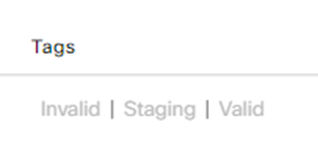
Once you have selected the validation state for each of the routers click the button in the upper left corner that says “Send to Controllers”. This will send the validation information to each of the controllers.
At this point everything in the cloud is setup and ready for the routers to onboard. To recap, we first created the overlay controllers in the Self-Service portal. Then we went into the PnP server and added the vEdge routers that we want to onboard. Finally, we went into vManage and imported those routers into vManage and set a validation status. Up until this point we haven’t put any configuration on the router(s). The final step is to bootstrap the routers so that they will reach out to vBond and join the SD-WAN overlay.
ROUTER BOOTSTRAPPING
The final step to onboarding a router via the PnP process is the bootstrap the router. So what is bootstrapping. Basically we are telling the router enough information to be able to connect to vBond. There are two ways to do this, the first way is the upload a cfg file to the router and reboot. ISR routers on bootup look for a file called ciscosdwan.cfg in bootflash and use it to bootstrap the router. I have created a template of what that file should contain:
Content-Type: multipart/mixed; boundary="day0bootstrap"
MIME-Version: 1.0
--day0bootstrap
Content-Type: text/cloud-config; charset="us-ascii"
MIME-Version: 1.0
Content-Transfer-Encoding: 7bit
Content-Disposition: attachment; filename="cloud-config-part"
#cloud-config
vinitparam:
- uuid : <udiProductId>-<udiSerialNumber>
- vbond : vbond-145576249.sdwan.cisco.com
- org : City of Hayward
--day0bootstrap
Content-Type: text/cloud-boothook; charset="us-ascii"
MIME-Version: 1.0
Content-Transfer-Encoding: 7bit
Content-Disposition: attachment; filename="cloud-boothook-part"
#cloud-boothook
system
system-ip <system-ip>
site-id <site id>
sp-organization-name "<organization name>"
organization-name "<organization name>"
vbond <vBond FQDN> port 12346
!
!
!
!
sdwan
interface <outside interface>
tunnel-interface
encapsulation ipsec weight 1
color <interface color>
exit
exit
!
!
ip name-server 208.67.220.220 208.67.222.222
!
!
interface <outside interface>
ip address < IP address | dhcp>
exit
!
ip route 0.0.0.0 0.0.0.0 <outside next-hop> !only needed if outside interface static IP!
!
interface Tunnel1
no shutdown
ip unnumbered <outside interface>
no ip redirects
ipv6 unnumbered <outside interface>
no ipv6 redirects
tunnel source <outside interface>
tunnel mode sdwan
exit
username <username> privilege 15 secret 0 <password>
!
--day0bootstrap--
Each of the variables in brackets would need to be changed based on the routers configuration, but this is enough info to get the router connected to the internet, and talking with vBond. The second method is to manually add this configuration to the router. One of the key differences between normal IOS-XE and SD-WAN IOS-XE is the notion of transactions. You need to commit any changes after they are staged, and the configuration is configured under the config-transaction mode.
Log into the router and in exec mode type configuration-transaction. Then paste the configuration above starting from the #cloud-boothook section and ending before the –day0bootstrap– . Finally you must commit these changes with the command commit. The router will now begin reaching out to vBond without the need to reboot the router.
CONFIGURATION BREAKDOWN
Now that we know what to configure, lets walk though the configuration and point out the different components needed for onboarding:
system
system-ip <system-ip>
site-id <site id>
sp-organization-name "<organization name>"
organization-name "<organization name>"
vbond <vBond FQDN> port 12346
This top section defines the unique system attributes for the router. In order for a router to join the overlay it needs to know its system-ip (think router-id for any routing protocol), site-id, the organization name as listed in the self-service portal, and which vBond controller to talk to. As you can see the vBond controller is listening on port 12346 for any new connections.
ip name-server 208.67.220.220 208.67.222.222
!
!
interface <outside interface>
ip address < IP address | dhcp>
exit
!
ip route 0.0.0.0 0.0.0.0 <outside next-hop> !only needed if outside interface static IP!
!
interface Tunnel1
no shutdown
ip unnumbered <outside interface>
no ip redirects
ipv6 unnumbered <outside interface>
no ipv6 redirects
tunnel source <outside interface>
tunnel mode sdwan
Skipping the middle section for now, the bottom section is the physical interface and tunnel interface section. It should go without saying, but in order for the router to connect to the cloud controllers it has to have some IP connectivity to the internet. This section configures the DNS servers so that the router can resolve the vBond FQDN, the interface configuration (either static or dhcp) for the interface that connects to the internet, and a tunnel interface that is used by the next section to form a tunnel to the controllers.
sdwan
interface <outside interface>
tunnel-interface
encapsulation ipsec weight 1
color <interface color>
This final section is the SD-WAN configuration section. In Cisco SD-WAN we have the notion of a TLOC, and this section defines the internet facing interface as a TLOC. The connections to the vSmart controllers use these TLOCs to form. To define a TLOC you need to know which interface the tunnel will form, the encapsulation type (ipsec vs GRE), and a color needs to be assigned.
VERIFICATION
Now that all of the configuration is done the router should be connected to the internet using the interface defined in the bootstrap config. Then in vManage under Monitor > Devices you should start to see device information start to populate.

Before a router connects to the controllers all that will be visible in this list is basic router configuration that is derived from the PnP sync process. Once a router is fully onboarded you will start to see information around reachability, CPU and memory load, the number of control connections and BFD sessions. The first thing to look for is reachability as it takes time for the rest of the information to populate. So if reachability shows up, you know you have made a successful connection.

If after some time a router doesn’t show up, I suggest connecting directly to the router and begin troubleshooting using the same IOS-XE network connectivity commands for any router.
Hope this helps you out, and good luck!
If you or your company are interested in learning more, please reach out to us at LookingPoint at sales@lookingpoint.com, we can help!

Trevor Butler, Network Architect